CAN-Connected DC Load Controller
A four-channel, RV-C-controlled 12 V load controller and the path a command takes from the CAN bus through a protected PWM output to the load it drives.
In production · many units in the field
I developed a four-channel embedded controller that switches and dims 12 V DC loads over an RV-C network, and it is in production now, with many units already out in the field. The work started with STM32 firmware bring-up, but the way I think about the controller is as one path. A command arrives on the bus, gets routed to the right instance, becomes a protected output, and the load on the far end either responds or it doesn’t. Every piece of the firmware and every test exists to make that path hold, and production means it has to hold on every unit, not just the one on my bench.
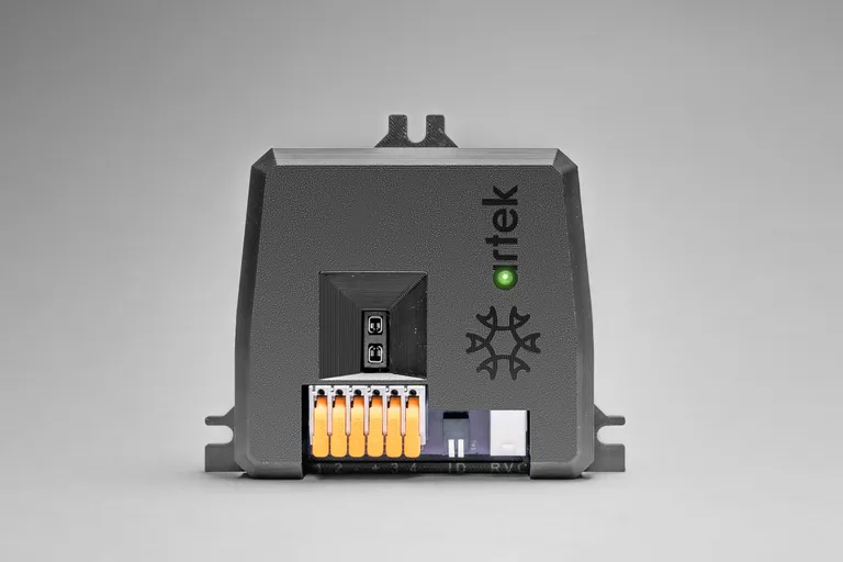
The first stretch of the path is protocol work. RV-C is the RV industry’s application layer on top of CAN: 29-bit identifiers at 250 kbit/s, each message carrying a data group number that says what kind of message it is and a source address that says who sent it. A command to dim a load does not name a controller. It names an instance, a small integer identifying one logical load on the network, and a four-channel controller is really four instances that happen to share a circuit board. So the controller’s first job on every frame it receives is to decide whether the message concerns one of its instances at all and, if so, which channel that instance maps to. It also has to talk back, reporting status for each instance so the rest of the network can see what the load is doing. The same CAN connection carries A/B firmware updates: a new image is written into the inactive half of flash while the current one keeps running, checked, and only then made the boot image, with the old one kept as a fallback. The bus that tells the controller what to do is also the bus that replaces its program, which is a convenience with a long list of things that must not go wrong, and the list matters more once the controller is in the field. On a bench unit, an update that dies halfway through is an inconvenience. On a fielded one, without a second image to fall back on, it would leave four loads that no longer respond to anything.
From the instance, a command becomes something physical. Dimming and fades come from timer-based PWM: the output is switched fully on and fully off hundreds or thousands of times a second, and the fraction of each cycle spent on sets the brightness the eye perceives. A fade is just that fraction ramped over time. The switching is done by a smart high-side switch, which sits between the supply and the load rather than between the load and ground. That placement matters in a vehicle, where the chassis is the return path. A wire chafing through to the frame becomes a short to ground that a high-side switch sees as overcurrent and interrupts, instead of a load that is suddenly and permanently on. “Smart” means the switch measures its own current, limits it, shuts down on overtemperature, can tell an open load from a connected one, and reports all of that over SPI. It also expects to be checked on: if the firmware stops servicing the switch’s watchdog, the switch assumes the firmware is gone and drops into a defined fail-safe state on its own. Faults therefore belong to this stretch of the path rather than sitting outside it. The firmware decodes the diagnostics the switch reports and handles recovery, because a protected output that can’t say why it turned off is only half protected.
Confirming that the load actually responds takes more than one kind of testing. The work combines automated host tests, hardware-in-the-loop tests, and manufacturing checks, and none of them can do the others’ job. The host tests run on a development machine with no hardware attached and cover the protocol and the tooling: whether a frame is parsed into the right instance and command, whether status goes out encoded the way the standard says. The board tests put real frames on a real bus and exercise commands against the state the controller reports back. Neither of those can see the load, so fixture and bench checks are what verify that it physically responds, with current actually flowing in a wire. Production adds a distinction the bench never forced. Host and board tests answer whether the design and the firmware are right. A manufacturing check answers a narrower question that has to be asked of every unit separately, whether this one was built the way the design says, because a cold solder joint or a connector that didn’t seat can hide inside a board that answers every command correctly.
The most useful failures are the ones where everything upstream looks right. The CAN traffic is correct, the timer registers hold the right duty cycle, and the load still does the wrong thing. A CAN acknowledgment only says that some controller on the bus received a valid frame; a PWM register only says what the microcontroller intends. Between that intention and a lamp are the SPI link to the switch, the switch’s own protection logic, the power rail feeding it, the differences between one assembled board and the next, and the load itself. On a bench, the last two are constants: one board, one set of test loads. With many units in the field, they aren’t. Boards are built in quantity rather than one at a time, and the load on each output is whatever that installation wired to it. When a failure like that turns up, there is no single place to look, so protocol timing, peripheral configuration, the switch’s diagnostics, the power rails, assembly differences, and the load have to be checked as parts of the same system, not as a list of suspects to clear one at a time.
- Embedded firmware
- CAN and RV-C
- Power electronics
- Diagnostics
- Hardware-in-the-loop testing
- Format
- Embedded systems development
- Threads
- Control systems · Power systems