Garmin–Victron Vehicle Control Integration
Developing Garmin-based vehicle interfaces that combine Victron power data, RV-C device control, and customer-specific automation.
Deployed integrations · ongoing platform development
A vehicle’s electrical architecture is a diagram the operator should never have to read. I develop Garmin-based interfaces that combine Victron power data with RV-C devices and vehicle controls, and most of that work is translation: programming customer-specific systems, mapping device state and commands, and turning the architecture into controls someone can use without knowing every component behind them.
Two horizontal buses. The upper bus is RV-C, with the Garmin display, lighting, climate, tanks, and switching on it. The lower bus is Victron’s CAN, with the battery and its BMS, the inverter/charger, and the solar chargers on it. A GX device joins them: one CAN port on each bus, one port isolated, bridged in software. State of charge and status flow from the Victron bus up to RV-C, where the display reads them; commands flow from the display down to the Victron equipment.
The architecture underneath has a shape worth drawing. The Victron equipment speaks Victron’s own CAN protocol and the battery management system has a CAN protocol of its own; the lighting, climate, tank, and switching devices speak RV-C; and the Garmin display speaks RV-C too. The hub that reconciles them is a Victron GX device with more than one CAN port, one of them electrically isolated, so that protocols sharing a bit rate and a cable type but not an identifier space are kept physically apart and bridged in software instead of colliding on a wire. The GX device publishes battery state of charge, inverter and charger status, and the rest of the Victron data onto the RV-C network, where the Garmin display reads it the same way it reads a tank sensor, and commands from the display reach the Victron equipment by the same road in reverse. Every device keeps speaking the language it was built for. The integration is the part that keeps the dictionaries straight.
On the Noovo Next platform, that meant supporting its move from 12 V to 48 V power while building a fully branded Garmin interface for lighting, climate, power, connectivity, and system monitoring. The voltage change is not a detail. At four times the voltage, the same power moves at a quarter of the current, which means smaller conductors and less heat in them for the same loads, and real headroom for the large ones. It also means every 12 V device still on the vehicle now sits behind a DC-DC converter, every switching output has to be rated for the new bus, and the interface has to understand that the power system it reports on has two voltage domains rather than one. We extended Garmin’s framework with an embedded HTML interface for the vehicle controls, which lets a control the framework doesn’t provide be built as a web page and shown on the same display.
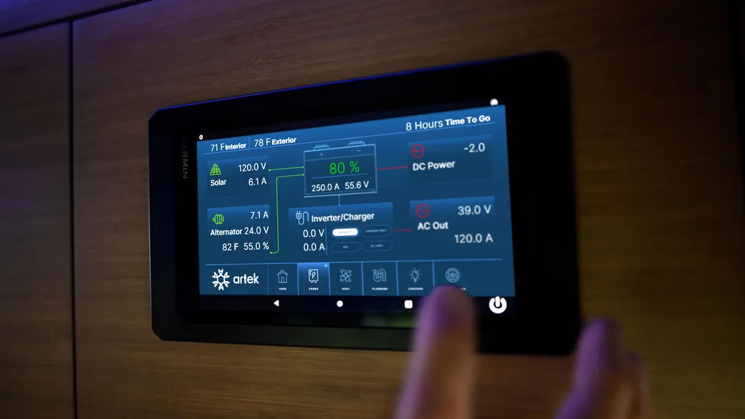
The screen is the visible part. Underneath it, shore-power availability, battery state, temperature, and what the user is asking for can all change which loads should run and which energy source is appropriate at that moment, and the control rules have to coordinate those responses rather than let each one act on its own. In the version of this work that Victron wrote up, plugging into shore power is what permits the air conditioner and the electric heater; dropping below a state-of-charge threshold is what sheds them again and hands heating back to the furnace; and a cabin temperature range the owner sets is what keeps a dog safe in a parked vehicle. Each of those is one rule with inputs from more than one vendor’s equipment. I test those rules against real hardware and against firmware updates, because an update to any one vendor’s device can change the timing or the meaning of a message the rule depends on, checking that what the interface says matches the state of the power system and of the physical vehicle it is mounted in.
- Human-machine interfaces
- CAN and RV-C
- Embedded web interfaces
- Energy-aware automation
- OEM integration
- Format
- Embedded interface integration
- Threads
- Control systems · Power systems